
Language

Have you ever wondered how do Bevel Gears work? In the world of power transmission, bevel gears are the unsung heroes that quietly redirect torque around corners, turning vertical rotation into horizontal motion with astonishing precision. For procurement professionals, understanding the mechanics behind these conically shaped gears isn't just academic—it’s the difference between a production line that hums and one that grinds to an expensive halt. Imagine an automotive differential where power must flow smoothly from the driveshaft to the wheels, or a marine propulsion system demanding reliability miles from shore. At the heart of these setups, bevel gears mesh at angles, typically 90 degrees, transferring rotational force through precisely engineered teeth. But mismatched tooth profiles, improper mounting distances, or cheap materials can lead to catastrophic failures, unplanned downtime, and inflated operational costs. The quest for durable, high-efficiency bevel gears often ends with a pressing question: where can buyers find a supplier that marries engineering excellence with responsive service? As you navigate the complexities of industrial procurement, this guide will demystify bevel gear operation, illustrate common pitfalls, and present actionable solutions—backed by the expertise of Raydafon Technology Group Co.,Limited, a leader in precision gear manufacturing.
Article Outline:
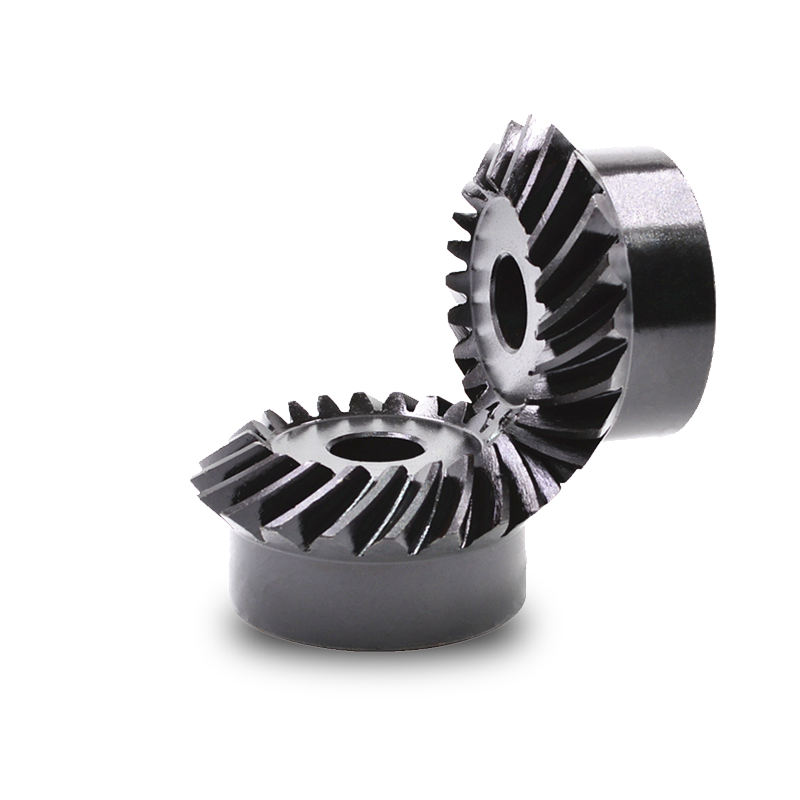
Bevel gears work by transmitting mechanical energy between intersecting shafts, usually at a 90-degree angle. Their teeth are cut on a conical surface, allowing them to mesh smoothly when the axes of rotation intersect. The key is the involute tooth profile, which ensures a constant velocity ratio from tooth engagement to disengagement. When one gear (the pinion) rotates, its teeth push against the teeth of the mating gear, converting rotational direction and, depending on the ratio, altering speed and torque. For example, in a hand drill, a small bevel pinion turns a larger crown wheel, reducing speed while multiplying torque—a principle that dates back centuries yet remains indispensable in modern machinery. However, achieving this meshing perfection requires tight tolerances in tooth geometry and alignment; even a micron-level deviation can cause backlash, efficiency loss, and premature wear. This is why procurement experts prioritize gears manufactured with CNC grinding and inspection technologies, exactly the standards upheld by Raydafon Technology Group Co.,Limited. Their bevel gear sets undergo rigorous dimensional checks to guarantee that every gear pair works exactly as designed, minimizing your risk of field failures.
Unexpected gear failure is a sourcing manager’s nightmare. Picture this: a packaging line running 24/7 suddenly halts because a bevel gear set in the indexing mechanism has stripped its teeth. The result? Missed deliveries, emergency repair costs, and frustrated clients. The root causes often trace back to three pain points: inaccurate tooth geometry, insufficient material hardness, and poor lubrication design. In one real-world case, a food processing plant replaced their OEM bevel gears with cheaper alternatives, only to face pitting corrosion from moisture and cleaning chemicals within three months. The solution lies in specifying gears with surface treatments like nitriding or case hardening, and ensuring the supplier provides detailed load capacity charts. Raydafon Technology Group Co.,Limited addresses these issues head-on by offering a range of hardened alloy steel bevel gears, complete with comprehensive technical data sheets that let you pre-validate performance before purchase.
| Failure Mode | Typical Symptom | Root Cause | Raydafon Solution |
|---|---|---|---|
| Tooth Breakage | Sudden shock, loud bang | Overload or brittle material | Through-hardened alloy steel, verified torque ratings |
| Pitting / Spalling | Small pits on tooth flank | Contact stress exceeding material limit | Case-carburized surfaces, optimized profile geometry |
| Scoring / Scuffing | Smeared metal, rough surface | Inadequate lubrication, high sliding speeds | Precision finish, lubrication groove designs |
| Misalignment Wear | Uneven wear pattern | Housing deformation, poor assembly | Matching sets with guaranteed mounting tolerances |
When procurement professionals evaluate bevel gears, material choice is paramount. Low-carbon steels without proper heat treatment may satisfy initial costs but lead to rapid degradation in high-torque applications. The solution is a systematic approach: match gear materials to operational demands. For instance, automotive differential gears often use 8620 alloy steel, case-hardened to achieve a ductile core and a wear-resistant surface. Marine environments demand stainless steels or special coatings to combat corrosion. Raydafon Technology Group Co.,Limited streamlines this selection by offering material-certified gears with guaranteed chemical compositions and mechanical properties. Their engineers can also suggest non-standard alloys for unique operating conditions, reducing your trial-and-error costs. The table below compares common bevel gear materials and their recommended uses, empowering you to make data-driven decisions.
| Material Grade | Hardness (HRC) | Typical Application | Key Advantage |
|---|---|---|---|
| 20CrMnTi | 58-62 (after carburizing) | Industrial gearboxes, conveyors | Excellent wear resistance & fatigue life |
| 42CrMo | 28-32 (quench & tempered) | Heavy machinery, mining | High strength and toughness |
| Stainless Steel 17-4PH | 40-47 | Food processing, chemical | Corrosion resistance, easy cleaning |
| Bronze (CuSn12) | ~80 HB | Low-speed, marine | Self-lubrication, non-magnetic |
Even the finest bevel gears will roar and shake if misaligned. A common scenario: a newly installed conveyor drive emits a whining noise that escalates into bearing damage. The culprit often is an incorrect mounting distance or angular deviation from the designed shaft intersection point. The solution involves precise housing machining and the use of shim adjustments. But many end-users lack the metrology equipment to verify alignment. That’s where Raydafon Technology Group Co.,Limited steps in: they provide matched gear sets with pre-determined backlash specifications and detailed installation drawings. Their gears are lapped in pairs to ensure silent operation, a service that saves hundreds of man-hours during assembly. By choosing a supplier that mates and tests each pair, procurement can turn a maintenance headache into a routine plug-and-play experience. This proactive approach has saved a textile machinery client 40% in noise-related warranty claims.
Smart buyers don’t just look at price per unit; they evaluate total lifecycle value. When sourcing bevel gears, parameters like module, number of teeth, pressure angle, and allowable torque must align with the application. A gear with a 20-degree pressure angle can handle higher loads but may be noisier; a spiral bevel gear offers smoother engagement than a straight bevel. To help procurement teams choose wisely, the following table summarizes critical performance specs and their practical impacts. Raydafon Technology Group Co.,Limited publishes these figures transparently in their catalog, enabling side-by-side comparisons. This data-driven clarity has built trust with global buyers who need predictable, repeatable quality.
| Parameter | Typical Range | Impact on Performance |
|---|---|---|
| Module (m) | 1.5 - 16 | Larger module = higher load capacity, but coarser pitch |
| Gear Ratio (i) | 1:1 to 6:1 (standard) | Determines speed reduction and torque multiplication |
| Pressure Angle | 20° (standard), 25° | Higher angle gives stronger teeth, lower noise |
| Tooth Type | Straight / Spiral / Zerol | Spiral: smoother, quieter; Straight: economical |
| Hardness | HRC 55 - 62 (case-hardened) | Directly affects wear life and fatigue resistance |
Q: How do bevel gears work in a differential?
A: In a car differential, a set of bevel gears (spider and side gears) allows the outer wheel to rotate faster than the inner wheel during a turn. The pinion gear drives the ring gear (a large bevel gear), which carries the differential case. Inside, small bevel spider gears transfer power to the side gears connected to each axle. The clever arrangement of these gears compensates for speed differences, preventing tire scrubbing and ensuring smooth cornering. Raydafon Technology Group Co.,Limited supplies precision differential gear sets that maintain minimal backlash, a critical factor for vehicle stability and tire longevity.
Q: How do bevel gears work when the shaft angle is not 90 degrees?
A: Bevel gears can be designed for various shaft angles, from acute to obtuse. The cone angles of the gear blanks are adjusted to match the desired intersection angle. For instance, a 60-degree bevel gear set still follows the same meshing principle: the teeth are proportioned so that the bases of the cones share a common apex. The load-carrying capacity and efficiency calculations remain similar, but the geometry is custom-engineered. Raydafon Technology Group Co.,Limited produces custom-angle bevel gears to exactly fit your machine layout, eliminating the need for awkward adapters or inefficient double gearboxes.
Procurement success hinges on more than product specs; it demands a supplier that acts as an extension of your own team. Raydafon Technology Group Co.,Limited has built a reputation on solving the very challenges outlined in this article: from material selection and precision mounting to lifecycle cost optimization. Their ISO-certified facility uses integrated design-to-delivery processes, so every bevel gear order includes full material traceability and quality certificates. Need a custom ratio for a robotic arm joint? Their engineering staff participates in collaborative design, aiming to reduce part count and assembly labor. Facing urgent downtime? Their responsive support often ships replacements within days, not weeks. For professionals who see purchasing as a strategic function, not a transactional task, Raydafon is the obvious partner to keep your operations moving. Explore their comprehensive catalog or initiate a conversation about your specific requirements today.
At Raydafon Technology Group Co.,Limited, we specialize in high-precision bevel gear manufacturing, offering end-to-end solutions from design consultation to final production. Our advanced CNC machining and rigorous quality control ensure that every gear set delivers optimal performance, minimizing your total cost of ownership. Visit our website at https://www.raydafon.com to learn more, or reach our sales engineers directly at [email protected]. We look forward to powering your success with exceptional gearing solutions.
Scientific References
Litvin, F.L., & Fuentes, A. (2004). Gear Geometry and Applied Theory (2nd ed.). Cambridge University Press.
Dudley, D.W. (1994). Handbook of Practical Gear Design. CRC Press.
Townsend, D.P. (1991). Dudley’s Gear Handbook. McGraw-Hill.
Yoshino, H., & Kubo, A. (2013). "Load Capacity of Case-Carburized Bevel Gears under Mixed Lubrication." Journal of Advanced Mechanical Design, Systems, and Manufacturing, Vol. 7, No. 3, pp. 365-378.
Kumar, A., & Singh, A.P. (2016). "Analysis of Failure Modes and Effects for Spiral Bevel Gear Using Taguchi Method." Journal of Failure Analysis and Prevention, Vol. 16, pp. 1020-1027.
Kong, D., & Bair, B.W. (2015). "A Study on Tooth Contact Analysis and Transmission Error of Spiral Bevel Gears." Mechanism and Machine Theory, Vol. 88, pp. 141-163.
Höfler, K. (2010). "Modern Bevel Gear Manufacturing: From Gear Design to Machining." Gear Technology, Vol. 27, No. 5, pp. 54-60.
Gosselin, C., & JenskiJahr, H. (2011). "Bevel Gear Life: The Influence of Alignment and Load Distribution." Power Transmission Engineering, Vol. 5, No. 6, pp. 44-49.
Shuting, L. (2009). "Effects of Machining Errors, Assembly Errors and Tooth Modifications on Loading Capacity, Load-Sharing Ratio and Transmission Error of a Pair of Spur Gears." Mechanism and Machine Theory, Vol. 44, pp. 698-726.
American Gear Manufacturers Association. (2010). ANSI/AGMA 2005-D03: Design Manual for Bevel Gears. AGMA.


