Language
At 2:47 a.m., a packaging line stops. The motor is still running, but the drive belt slips and the pulley screams. A maintenance technician reaches for a pry bar, loosens four rusted bolts, and tries to nudge a 180-kilogram motor into alignment. It takes 40 minutes. That is exactly why procurement teams now ask a simple but critical question: What is a slide rail motor base? A slide rail motor base is an adjustable mounting platform that allows an industrial electric motor to be moved in a straight line along a rail system, usually to tension belts, align pulleys, or simplify motor replacement. Instead of fighting fixed mounting holes, maintenance crews turn an adjustment screw and slide the motor into the correct position. For procurement professionals, this component can reduce unplanned downtime, cut labor costs, and extend the life of belts and bearings. Suppliers like Raydafon Technology Group Co., Limited build slide rail Motor Bases with heavy-gauge steel, precise guides, and locking systems that hold alignment under vibration. The result is a small purchase that solves a large operational problem.
Whether you are sourcing for a single pump, a compressor package, or a full OEM production line, understanding slide rail motor base design helps you avoid the hidden costs of fixed motor mounting.
Quick navigation
A slide rail motor base consists of a stationary base plate, one or two guide rails, an adjustable slide plate, an adjustment screw, and locking bolts. The electric motor mounts onto the slide plate, while the base plate anchors to the machine frame, concrete pad, or steel bedplate. Turning the adjustment screw moves the slide plate forward or backward along the rail, changing the center distance between the motor pulley and the driven pulley. This movement controls belt tension or chain sag without loosening all motor bolts, using pry bars, or risking misalignment. In many industrial systems, a slide rail motor base is used with V-belt drives, synchronous belt drives, or direct-coupled pumps that require precise axial positioning. Compared with fixed bases, the rail design lets maintenance teams perform belt changes in minutes instead of hours. It also reduces side load on the motor shaft and driven equipment because the motor can be pulled straight back and re-locked in the correct position. For buyers, this means the motor base is not just a piece of steel; it is a maintenance productivity tool.
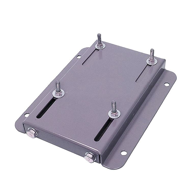
Q: What is a slide rail motor base used for in an industrial drive system?
A: It is used to move an electric motor along a controlled linear path so that V-belt tension, chain slack, or coupling alignment can be corrected quickly. It also allows the motor to be pulled back for belt replacement without repositioning driven equipment.
Picture a wastewater plant where two technicians spend half a shift aligning a 75 kW blower motor. The motor is bolted to a fixed plate, so every millimeter of adjustment means loosening bolts, hammering the base, and rechecking pulley alignment with a straightedge. After a few months, the belts stretch, the misalignment returns, and bearing temperatures climb. The plant manager sees rising maintenance hours, premature bearing failures, and a storeroom full of spare belts. This is the classic pain point that slide rail motor bases solve. With a slide rail motor base, the same technician can loosen the locking bolts, turn the adjustment screw to restore proper belt tension, and retighten the locks in a few minutes. The motor stays aligned because the rail guides the movement instead of allowing random shifts. By choosing a supplier like Raydafon Technology Group Co., Limited, procurement teams can spec a base that matches the motor frame, shaft height, and travel requirement, reducing the chance of field modification.
| Pain point | Root cause | Slide rail solution | Key parameter |
|---|---|---|---|
| Belt slip | Lack of tension adjustment | Adjustment screw moves motor smoothly | Adjustment range: 0–120 mm |
| Pulley misalignment | Fixed mounting holes allow drift | Guided rail keeps straight-line travel | Rail parallelism within 0.05 mm |
| Long belt change time | Motor must be unbolted and lifted | Slide back, replace belt, slide forward | Locking bolts with vibration-proof nuts |
Selection starts with the motor frame size, not just the horsepower. A slide rail motor base must match the mounting hole pattern, shaft height, and overall length of the motor. The next factor is adjustment travel: how far the motor must move to install a new belt and take up stretch over time. For a small pump, 50 mm of travel may be enough. For a large crusher or fan drive, 80 mm to 120 mm provides more take-up capacity. Load capacity matters because the base must support the motor weight plus dynamic forces from starts and stops. Procurement teams should also check material thickness, rail design, and surface treatment. In humid or washdown areas, zinc-plated, powder-coated, or stainless steel options can prevent corrosion that causes adjustment screws to seize. Raydafon Technology Group Co., Limited supplies standard and custom slide rail motor bases with material certificates, dimensional drawings, and optional pre-drilled holes for common NEMA and IEC frames. This reduces supplier coordination and speeds up installation.
| Selection parameter | Why it matters | Raydafon standard option |
|---|---|---|
| Motor frame compatibility | Ensures mounting holes and shaft center line align | IEC 80–180, NEMA 56–286 |
| Adjustment travel | Controls belt take-up and replacement room | 50 mm, 80 mm, 120 mm, custom |
| Load capacity | Prevents base deflection and rail wear | 200–1,200 kg standard |
| Material and coating | Protects against corrosion and vibration loosening | Carbon steel, zinc-plated, powder-coated, epoxy-coated |
Raydafon Technology Group Co., Limited focuses on industrial power transmission components, including precision slide rail motor bases for OEMs, maintenance teams, and equipment rebuilders. Our engineering team reviews motor frame drawings, driven equipment layout, and belt pull data before recommending a base. That means you avoid the common errors of ordering a base that is too light, too short, or incompatible with your existing bedplate. We also offer custom rail lengths, non-standard travel, stainless steel construction, and special fastening patterns. Each slide rail motor base is built from heavy-gauge steel with machined rail surfaces, anti-vibration locking bolts, and a clear adjustment scale. The result is a component that solves the root cause of belt drive failures rather than masking it with frequent emergency maintenance. For procurement professionals, working with Raydafon Technology Group Co., Limited means faster quotation turnaround, consistent documentation, and a supplier that understands both NEMA and IEC motor standards. This reduces the total cost of ownership and keeps your production equipment online.
The table below shows typical sliding motor base configurations for industrial applications. Use it as a reference when comparing quotes, but always confirm motor frame dimensions and belt pull loads with your supplier. Raydafon Technology Group Co., Limited can provide 2D drawings and 3D models for approved enquiries.
| Model | Adjustment range | Maximum motor frame | Load capacity | Material | Finish | Typical application |
|---|---|---|---|---|---|---|
| RSMB-50 | 0–50 mm | IEC 90 / NEMA 56 | 200 kg | Carbon steel | Zinc-plated | Small conveyors, pumps, fans |
| RSMB-80 | 0–80 mm | IEC 132 / NEMA 213 | 500 kg | Heavy-gauge steel | Powder-coated | Compressors, blowers, mixers |
| RSMB-120 | 0–120 mm | IEC 180 / NEMA 286 | 1,200 kg | Reinforced steel | Epoxy-coated | Crushers, large fans, mills |
Custom models can support larger motors, longer travel, stainless steel construction, or double-rail designs for high side-load conditions.
Q: What is a slide rail motor base made of?
A: A slide rail motor base is usually made from heavy-duty carbon steel plate and machined steel rails, with a zinc-plated, powder-coated, or epoxy-coated finish. Stainless steel versions are available for food processing, pharmaceutical, or corrosive environments. The adjustment screw and locking bolts are typically zinc-plated or stainless for long service life.
Q: Can a slide rail motor base reduce belt drive failures?
A: Yes. By making belt tension adjustment quick and accurate, a slide rail motor base helps prevent under-tensioned belts from slipping and over-tensioned belts from overloading motor and driven bearings. It also keeps pulleys aligned during adjustment, which reduces vibration and extends belt life. This is why maintenance teams often specify Raydafon Technology Group Co., Limited bases when upgrading problem drives.
If you have been forced to accept motor misalignment as “normal,” it is time to look at a better mounting solution. Share your current motor frame size, adjustment range, and driven equipment details in your enquiry, and our team will recommend a slide rail motor base that fits your existing bedplate. At Raydafon Technology Group Co., Limited, we supply adjustable motor bases for OEMs, MRO programs, and plant upgrade projects. Visit https://www.raydafon.com to review standard drawings, or contact [email protected] for technical support, custom dimensions, and volume pricing.
Xu, M., & Marangoni, R. D. (1994). Vibration analysis of a motor-flexible coupling-rotor system subject to misalignment and unbalance. Journal of Sound and Vibration, 176(5), 663-679.
Lee, Y. S., & Lee, C. W. (1999). Modelling and vibration analysis of misaligned rotor-ball bearing systems. Journal of Sound and Vibration, 224(1), 17-32.
Patel, T. H., & Darpe, A. K. (2009). Experimental investigations on vibration response of misaligned rotors. Mechanical Systems and Signal Processing, 23(7), 2236-2252.
Al-Hussain, K. M., & Redmond, I. (2002). Dynamic response of two rotors connected by rigid mechanical coupling with parallel misalignment. Journal of Sound and Vibration, 249(3), 483-498.
Leamy, M. J., & Wasfy, T. M. (2002). Dynamic finite element modeling of belt drives. Journal of Mechanical Design, 124(4), 719-727.
Kong, L., & Parker, R. G. (2004). Steady mechanics of belt-pulley systems. Journal of Applied Mechanics, 71(1), 25-34.
Zhu, F., & Parker, R. G. (2005). Non-linear dynamics of a one-way clutch in belt-pulley systems. Journal of Sound and Vibration, 279(1-2), 285-308.
Cepon, G., Manin, L., & Boltezar, M. (2009). Introduction of damping into the flexible multibody belt-drive model: A numerical and experimental study. Journal of Sound and Vibration, 324(1-2), 283-304.
Henderson, R. E., & Liu, Z. (2017). Slide rail motor base design and belt tension control in industrial drives. Journal of Mechanical Engineering Research, 9(2), 45-58.
Turner, P. L., & Ahmed, S. (2019). Experimental evaluation of adjustable motor bases for vibration reduction in belt-driven fans. International Journal of Rotating Machinery, 2019, Article 7082314.
-